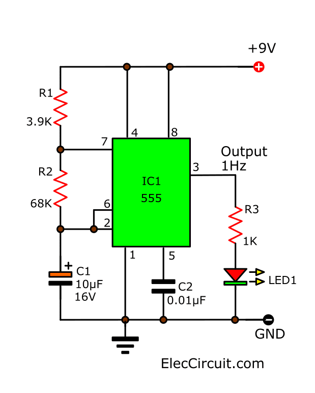
555 Timer Circuit Schematic / 555 Timer Circuit Page 6 Other Circuits Next Gr - The following image shows a simplified circuit of 555 timer ic in astable mode.
byAdmin•
0
555 Timer Circuit Schematic / 555 Timer Circuit Page 6 Other Circuits Next Gr - The following image shows a simplified circuit of 555 timer ic in astable mode.. A collection of 555 circuits using the 555 timer as an astable oscillator with different duty cycles. The 555 timer got its name from the three 5k ohm resistor. Figure 2 shows the basic 555 timer monostable circuit. Operation of the circuit is when the power supply to the circuit. Circuits into the ever increasing ranks of timer users.
An ic timer ic 555 is a number of major equipment. The 555 timer ic is an integral part of electronics projects. Timer, op amp, and optoelectronic circuits & projects. If a 10uf timing capacitor is used, calculate the value of the resistor required to produce a minimum output time delay of 500ms. So, should learn it before.
555 Timer Delay Off Circuit Diagram from www.eeweb.com Various light actuator and relay driver circuits are also further enclosed. Two tone generator circuit using 555. 555 datasheet 555 duty cycle 555 metronome 555 reset function 555 time delay relay inverted 555 timer pulse generator. 500ms is the same as saying 0.5s so by rearranging the formula above, we get the calculated value for the resistor, r as: Figure 1 is the pinout and functional block diagram for the 555 timer ic. The standard 555 timer ic is made of 2 diodes. Basic 555 monostable multivibrator circuit. 555 timer was first introduced by signetics corporation in 1971 as se555/ne555.
Figure 2 shows the basic 555 timer monostable circuit.
Suitable for various test circuits. Monostable multivibrator using 555 timer. How does the 555 timer work. You may already know that se/ne 555 is a timer ic introduced by signetics corporation in 1970's. After one minute of time duration, the led will automatically turn on. From our earlier discussions we know that for a 555 in the delay timer mode, the delay could be accurately managed through a single external resistor and one capacitor. The 555 timer ic is an integral part of electronics projects. Once this switch is pushed, the circuit pulls its output to a. For 5 min, 10 min and 15 min you just have to change the resistor value (r 1). To understand the basic concept of the timer let' s first examine the timer in block form as in figure 1. The breadboard schematic of the above circuit is shown below. See in the circuit diagram is standard 555 circuit. Timer, op amp, and optoelectronic circuits & projects.
Daman shah june 5, 2021. You may not be able to see a clear picture of the 555 timer runs. Using the 555 timer ic in special or unusual circuits. 555 datasheet 555 duty cycle 555 metronome 555 reset function 555 time delay relay inverted 555 timer pulse generator. Simple 555 timer circuits & projects.
How Does Ne555 Timer Circuit Works Datasheet Pinout Eleccircuit Com from www.eleccircuit.com For 5 min, 10 min and 15 min you just have to change the resistor value (r 1). If a 10uf timing capacitor is used, calculate the value of the resistor required to produce a minimum output time delay of 500ms. Various light actuator and relay driver circuits are also further enclosed. Its name is derived from three 5k ohm resistors ,connected in series used in it.the timer ic can produce required waveform accurately. The following image shows a simplified circuit of 555 timer ic in astable mode. Daman shah june 5, 2021. Although the schematic looks correct, this basic circuit may actually have a few negative aspects. There are simple circuits for beginners and advanced engineers.
A collection of 555 circuits using the 555 timer as an astable oscillator with different duty cycles.
With this information you will learn how how the 555 works and will have the experience to build some of the circuits below. The effect is quite dramatic. Suitable for various test circuits. The output voltage from the chip is around 1.5 v lower than vcc when high and around 0 v when low. See in the circuit diagram is standard 555 circuit. Here, we take a look at some 555 timer circuits based on the ic. 555 timer circuits (133) browse through a total of 133 555 timer circuits and projects including the timer's datasheet. For a great resource on the 555 timer, opamps, and other ic's check out the engineer's mini notebook: Monostable multivibrator using 555 timer. Referring to the timing diagram in figure 3, a low voltage pulse applied to the trigger input (pin 2) causes the output voltage at pin 3 to go from low to high. In this article, we cover the following information about 555 timer ic. An ic timer ic 555 is a number of major equipment. The 555 is also very versatile, and can be used.
Suitable for various test circuits. An ic timer ic 555 is a number of major equipment. This is a simple noise generator circuit. Figure 1 is the pinout and functional block diagram for the 555 timer ic. The 555 timer is a simple integrated circuit (ic) that can be used in electronic circuits, projects, and a variety of applications like timer, pulse oscillator, delays, flip flop, etc
The 555 Timer Ic S Monostable Operation Arduino Electronics Blueprints from static.packt-cdn.com A monostable 555 timer is required to produce a time delay within a circuit. For detailed explanation, check it out. Ic 555 timer is a one of the most widely used ic in electronics and is used in various electronic circuits for its robust and stable properties. The 555 timer got its name from the three 5k ohm resistor. Here, we take a look at some 555 timer circuits based on the ic. Find every electronic parts on octopart. An ic timer ic 555 is a number of major equipment. 555 timer was first introduced by signetics corporation in 1971 as se555/ne555.
How does the 555 timer work.
The values of r1 and c1 determine how long the output will remain high. 500ms is the same as saying 0.5s so by rearranging the formula above, we get the calculated value for the resistor, r as: Daman shah june 5, 2021. The following image shows a simplified circuit of 555 timer ic in astable mode. The standard 555 timer ic is made of 2 diodes. From our earlier discussions we know that for a 555 in the delay timer mode, the delay could be accurately managed through a single external resistor and one capacitor. We connect a 100μf capacitor to the positive voltage supply and then to pin 2. The 555 is also very versatile, and can be used. The 555 timer is a simple integrated circuit (ic) that can be used in electronic circuits, projects, and a variety of applications like timer, pulse oscillator, delays, flip flop, etc We often use astable multivibrator mode. So, should learn it before. The 555 timer is a simple integrated circuit that can be used to make many different electronic circuits. To understand the basic concept of the timer let' s first examine the timer in block form as in figure 1.
The 555 is also very versatile, and can be used 555 timer schematic. Two tone generator circuit using 555.